We now tackle the lowest of the six levels mentioned in the introduction -- the digital logic level.
First we will introduce propositional logic - `Boolean algebra'. Then we will show how simple logic (Boolean) functions are implemented in computer hardware.
Since at least 400 B.C. human beings have been studying what it means to think and to reason. Two closely related aims can be identified:
Broadly speaking, logic is the study of the principles and patterns of reasoning, argument and proof. Again generalising, we can say that logic uses a language that is a formalisation of certain types of natural language statements.
You should be aware that there are two distinct but related forms of logic:
if(x == 10
  && y == 20)
(test the truth of the logic statement x
is-equal-to 10 and y is-equal-to 20.
Propositional logic deals with statements (propositions) which make claims which can be either true or false. Thus, valid propositions are:
The test for validity is as follows: you must be able to meaningfully append to the statement "is true" (or "is false").
Thus "Dublin is the capital of Ireland is true".
Notice, however, how "Manchester United are Premiership Champions" may need time/date qualification.
The following are invalid propositions.
We can make symbols stand-for any proposition, e.g.
![]() . Hence, in propositional
calculus, the `Boolean' variable p has the truth value true.
. Hence, in propositional
calculus, the `Boolean' variable p has the truth value true.
![]() .
.
We can now combine elementary propositions using logic connectives to make compound or complex propositions.
Dublin is the capital of Ireland and Belfast has more than 100,000 inhabitants is true.
The combined proposition is true if-and-only-if both elements are true.
In this case, let us agree that both are true, so that the statement:
Arsenal are European Champions and Belfast has more than 100,000 inhabitants is false.
The meaning of and can be neatly summarised with a truth-table using abstract symbols:
Other symbols for conjunction are: ![]() (looks like an A), and, in
C/C++/Java,
(looks like an A), and, in
C/C++/Java, &&.
Note that or has two natural language meanings: exclusive-or, only one of the statements can be true at any time; inclusive-or, only either one or the other needs be to be true, or both; without any qualification, or generally means inclusive-or.
The meaning of or is given by the following truth-table:
Other symbols for disjunction: ![]() , and, in C/C++/Java,
, and, in C/C++/Java, ![]() .
.
If a proposition p is true, then not(p) is false.
The meaning of not is given by the truth-table:
Other symbols for negation: ![]() ,
, ![]() , and, in C/C++/Java,
, and, in C/C++/Java,
!.
[This section included only for completeness - not part of CSC 722.]
Let us have the proposition: Joe Bloggs is in first year and Joe Bloggs is QUB student.
And we know that the first year computing science class is in 1.15 at 9.30am on Thursdays.
Given that information, you and I can easily deduce a (relatively certain) plan on how to get in contact with Bloggs - i.e. hang about 1.15 at around that time.
But propositional logic cannot handle this problem. Let us simplify, the pattern is the same:
Socrates is a person (or Socrates is human) - a perfectly valid proposition.
All persons are mortal, i.e. they have a finite lifespan.This is not a valid proposition. It has, as we shall see, a variable hidden in it. "Socrates" is OK, but "person" can stand for any person and this is not allowed in propositional logic.
Therefore, Socrates is mortal - another valid proposition.
For this we need predicate calculus.
[This section is included only for completeness - not part of CSC 722.]
If you had gone to primary school before about 1965, you would have leaned to parse natural language sentences into: subject, predicate. Thus, Dublin (subject) is the capital of Ireland (predicate).
In predicate calculus we restrict the meaning of predicate to possession of a property or attribute, e.g. the property of being the capital of Ireland.
Predicate calculus then allows us to handle the statement:
All persons are mortal.
as
All persons have the property of being mortal.
which, making the variable explicit, expands to:
For all persons X, X has the property of being mortal.
Another example:
Some students get up early.
Some students have the property of getting up early.
which, making the variable explicit, expands to:
For at least one student Y, Y has the property of getting up early.
or
There exists a student Y, Y has the property of getting up early.
In terms of propositional logic, universal quantification can be explained by expanding/enumerating over all the cases:
For all persons X, X has the property of being mortal.
isMortal(person1) AND isMortal(person2) AND isMortal(person3)
AND ... up to the last person.
Since it is and, for the overall proposition to be true, all components must be true.
In terms of propositional logic, existential quantification can be explained by expanding/enumerating over all the cases:
There exists a student Y, Y has the property of getting up early.
getsUpEarly(student1) OR getsUpEarly(student2) OR getsUpEarly(student3)
OR ...  up to the last student.
Since it is or, for the overall proposition to be true, only one component need be true.
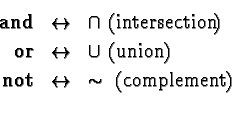
The propositional calculus on truth values is equivalent to
(isomorphic with) the calculus of set operations:
Digital computers are constructed from switching circuits which implement propositional calculus - Boolean algebra; indeed, the term switching algebra is sometimes used. `Switch-on' might be associated with true and `off' with false. However, equally, so long as everyone is agreed as to the convention, `on' could be associated with false and `off' with true.
Likewise, the physical entities representing the values could be {voltage-low, voltage-high} or {light-off, light-on}, or whatever. Very often, we use {0, 1} - the binary digits - to represent {false, true}.
The essence of Boolean algebra is that we have only two allowable values, which we can label whatever we like, usually: {false, true}, or {0, 1}, and the two binary operations mentioned above: conjunction (and), and disjunction (or), together with the unary operation negation (not). There are other binary operations, but they can be expressed in terms of these three.
Let us now examine these operations or functions - to emphasise that they are functions, we write them in prefix notation, remarking, however, that the infix notation conveys exactly the same meaning. In addition, we use the value set {0,1}, recalling that the set {false, true} is entirely equivalent.
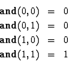
Of course, this is the same thing as Table 3.1.
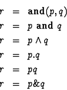
Because there is a slight analogy with numerical multiplication, and
is sometimes denoted by the infix `.', or just concatenation of the input
variables; also, and itself is often written in infix form. Thus, for
Boolean variables p, q, and r, the following are
equivalent:
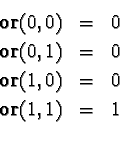
Of course, this is the same thing as Table 3.2.
Because there is a slight analogy with numerical addition, or is
sometimes denoted by `+'. Thus, for Boolean variables p, q, and
r, the following are equivalent:
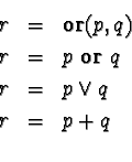

This is the same thing as Table 3.3.
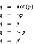
Because there is a slight analogy with numerical negation, or is
sometimes denoted by variations of - and ![]() . Thus, for Boolean variables
p, q, the following are equivalent:
. Thus, for Boolean variables
p, q, the following are equivalent:
The analogies with arithmetic (and `ordinary' algebra) may cause confusion
for the unwary; remember that ![]() stand for
stand for ![]() and that it makes no sense at all to do
arithmetic on them - no more sense than, for example, attempting to multiply a
Java text
and that it makes no sense at all to do
arithmetic on them - no more sense than, for example, attempting to multiply a
Java text String by, say, 25.
Although it is not uncommon to see ![]() , you must remember that both or
and and are binary - meaning two parameter functions. Thus,
strictly,
, you must remember that both or
and and are binary - meaning two parameter functions. Thus,
strictly,
if(x==2||y==3||z==4) strictly could be
written if(x==2||(y==3||z==4)).
Of course, in `ordinary' algebra, + and ![]() -, etc. are also
binary, but the associative law, see section 3.3.2
for these operations allows us to string a series of them together. Note: in
`ordinary' algebra, there are two minuses, a unary one (-1) and a binary one (3
- 1 = 2); always remember that if you have to write an expression evaluator
program.
-, etc. are also
binary, but the associative law, see section 3.3.2
for these operations allows us to string a series of them together. Note: in
`ordinary' algebra, there are two minuses, a unary one (-1) and a binary one (3
- 1 = 2); always remember that if you have to write an expression evaluator
program.
Just as it helps to know that in ordinary algebra, ![]() , or that x + (-x) = 0, it is useful to be
aware of the more useful equivalences (or identities or laws) of Boolean
algebra. Some of them are shown in Table 3.4.
Some of these are intuitive, some not. For each equivalence there are duals -
where and is swapped for or and vice-versa. For
completeness, we show the table in two forms, Table 3.4,
using the mathematicians
, or that x + (-x) = 0, it is useful to be
aware of the more useful equivalences (or identities or laws) of Boolean
algebra. Some of them are shown in Table 3.4.
Some of these are intuitive, some not. For each equivalence there are duals -
where and is swapped for or and vice-versa. For
completeness, we show the table in two forms, Table 3.4,
using the mathematicians ![]() notation, and Table 3.5,
using the engineers
notation, and Table 3.5,
using the engineers ![]() notation.
notation.
|
We have already shown truth-tables for and, or and not - Tables 3.1, 3.2, and 3.3. They can also be used for proving results like those above.
Example. Verify: p + p.q = p
|
Comparison of columns 4 (p) and 5 (p + p.q) proves the result.
Exercise. Use a truth-table to prove
![]() .
.
How many rows in a truth-table? In the example above, we have two input
variables, ![]() , hence we have 22 rows - these
enumerate all the possibilities of
, hence we have 22 rows - these
enumerate all the possibilities of ![]() , where
, where ![]() can take
on values from only
can take
on values from only ![]() .
.
Ex. How many rows for a truth-table involving ![]() ?
? ![]() ?
? ![]() ?
? ![]() ?
?
Ex. In integer arithmetic, you want to prove that x.y + (-x).y = 0. Is it possible to do this using a table? Hint: how many rows?
Logic gates are the hardware implementation of logic functions. Again, all Boolean functions can be implemented using a combination of and, or, and not gates. The term gate comes from the operation of the and gate, see below, which, if one of its inputs is false, blocks or gates the other input, even if it is true.
Microprocessors, and other digital logic integrated circuits (chips) are simply massive collections of interconnected gates.
Because of a particular twist of fate in the physics of transistors - of which logic gates are constructed - it turns out that real circuits tend to employ nand and nor gates a good deal in preference to and and or:
[A good many of the figures in the remainder of this chapter are from [Tanenbaum, 1999], chapter 3].
For completeness, we show transistor implementations of not (also called an inverter), nand and nor. Again for completeness, we give the following model of a transistor when it is operated in so-called switching mode.
There are three connections - collector, base, and emitter. The positive power supply (e.g. +5 volts) is applied to the collector via a resistor; the emitter (the one with the arrow) is connected to ground/earth. The input signal is applied to the base. When the input signal is high, say > 3 volts when the power is 5 volts, the transistor switches on, i.e. current is allowed to flow down to the emitter and out to ground. When the input signal is low, the transistor switches off i.e. little or no current is allowed to flow.
The net effect of the transistor in Figure 3.1(a)
switching on is that the output is connected to ground and
Vout takes the voltage of ground - ![]() volts.
Thus high input (Vin) - logic 1 - yields
low output - logic 0; thus, not, inversion.
volts.
Thus high input (Vin) - logic 1 - yields
low output - logic 0; thus, not, inversion.
The net effect of the transistor switching off is that the output
takes on the voltage ![]() volts. Thus low input (Vin) - logic 0 - yields
high output - logic 1; thus, not, inversion.
volts. Thus low input (Vin) - logic 0 - yields
high output - logic 1; thus, not, inversion.
With this model in mind, it is easy to verify that the circuits in Figures 3.1(b) and (c) do in fact operate as nand and nor.
If you would like to see mechanical implementations of gates (levers, also water valves), see [Hillis, 1999].
Figure 3.2 shows the symbols, and truth-tables, for the five basic logic gates.
The circles denote negation - not, inversion. It is possible to have negation on inputs too.
There are two fairly distinct activities in working with digital logic, analysis, and synthesis.
This section covers analysis.
Example. What does the circuit in Figure 3.3 do?
It takes a majority vote over the three inputs.
Exercise. Verify the truth-table in Figure 3.3(a)
by creating an expanded truth table containing columns for ![]() . Note: starting from
scratch, and not knowing the answer, this is the way you would normally do it -
you cannot hope to work out column M in your head.
. Note: starting from
scratch, and not knowing the answer, this is the way you would normally do it -
you cannot hope to work out column M in your head.
Quite often, because of a preference for nand, nor, or because there are spare gates left over, it may be desired to implement and, or, and not using nand, nor. Figure 3.4 shows some examples.
Let us examine the nand gate (top) in Figure 3.4(a).
![]() .
.
Now the nand version (top) of Figure 3.4(b):
the input to the second gate is clearly ![]() , and we already know that, connected like this, the second nand
gate performs negation, and two negations cancel, hence AB.
, and we already know that, connected like this, the second nand
gate performs negation, and two negations cancel, hence AB.
Exercise. Use Boolean algebra to verify that the two circuits in Figure 3.4(c), do, in fact, perform or.
Exclusive-or, commonly abbreviated to xor, as opposed to inclusive-or,
see the discussion above, captures the meaning either one or the other, but
not both - i.e. it outputs a 1 if the inputs are different. We will have
cause to refer to it later, so it is worthwhile to show a circuit - Figure
3.5
shows three possible circuits and a truth-table. Figure 3.5(b)
directly implements the Boolean expression most usually associated with
xor: ![]() .
.
Integrated circuits started to appear in the late 1960s. A typical single chip of that age - but still available to buy today - is shown in Figure 3.6; it contains four nand gates and has 14 pins.
Nowadays, an integrated circuit such as Figure 3.6 is said to be small scale integrated (SSI). Small scale integrated circuits contain up to 10 gates (up to about 100 transistors). In the late 1960s, complete computers were made from SSI; still, this was a lot better than the individual devices (transistors, resistors, etc.) of the 1950s and 60s. And, a fantastic improvement over the vacuum tubes used in the 1940s.
You will still find SSI circuits, e.g. Transistor-transistor-logic (TTL) 74xx00 quad 2-input nand used on the periphery of computer systems, and as the `glue' which connects the more complex circuits/chips together.
In SSI chips, as many gates of a given type as possible are put in the
package (chip). The number of gates is limited by the number of pins, and to a
lesser extent by the ability to dissipate the heat generated by the circuit. On
the 74xx00 you have: power 2 pins + 4 x (2 inputs +
1 output) = 3 for each NAND gate = total of 14 pins. An additional
consideration is the area taken up by such an SSI chip, roughly ![]() .
.
In the case of early TTL each chip would consume about 10 milliWatts of power.
Later medium scale integrated (MSI) circuits began to appear - containing 10-100 gates. Later on large scale integrated (LSI) containing 100-100,000 gates. The first microprocessors (1971 - the 4 bit Intel 4004) would have been classified LSI. Now we have very large scale integrated (VLSI), and beyond. The latest Pentium III contains in the region of 10,000,000 transistors.
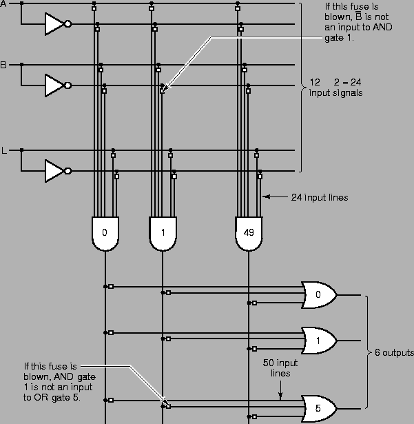
A great many very complex complete components are now available on single chips - microprocessors, disk controllers, modems, .... On the other hand, there is still a need to design circuits from simple gates. But, building large circuits from SSI is simply impractical - it would take too much space and consume too much power. Hence, programmable logic arrays (PLAs) and field programmable gate arrays (FPGAs).
A programmable logic array contains a large array of not, and gates and or gates on a single chip. The user can connect certain gates by breaking certain (fuse) connections. Figure 3.7 contains an example.
 |
if statement:
     int i;
     if( (i<=2) || (i>=5) )System.out.println(i);
(b) Explain, in plain English, the circumstances under which the 'THEN'
part gets executed, and i gets printed.
(c) Explain how de Morgan's law can be made to simplify (or at least make
it more understandable) the following Java if statement:
if( (i>12) || ( !(i<20) ) )System.out.println(i);
(d) Explain, in plain English, the circumstances under which the 'THEN'
part gets executed, and i gets printed.
if statement, as before int i;:
if( !(i<=92) || !(i>=100) )System.out.println(i);
(b) Explain, in plain English, the circumstances under which the 'THEN'
part gets executed, and i gets printed.
Note the error in the caption of Figure 3.5; it should read "Exclusive or".
What will be the power consumption?
(b) Draw a diagram for a two-input multiplexer -- see Figure 4.1.
(c) A four input multiplexer will have four inputs -- and one output; how many control lines (A, B, C, ...); again, see Figure 4.1.
(d) Sketch a diagram for a four-input multiplexer.
               Y-------------------NAND
                                   NANDo-----+
                    +-------NOTo---NAND      |
                    |                        +---NAND
                    |                            NANDo--- F
                    |                        +---NAND
                    +--------------NAND      |
                    |              NANDo-----+
               Z-------------------NAND
                    |
                    S
[Note:         |
          -----+------  these lines are connected
               |
          ------------  these lines are NOT connected]
               |
               A-----------+--------AND
                           |        AND------+
                    +---------------AND      |
                    |      |                 |
                    |      +--------AND      +--OR
               B----+               AND----------OR--- F
                    |      +--------AND      +--OR
                    |      |                 |
                    +---------------AND      |
                           |        AND------+
               C-----------+--------AND