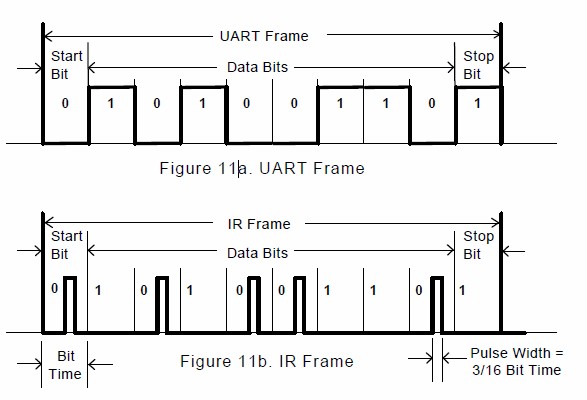
In Figure 11a, the signal to the left of the UART [0] will not be discussed. The signal between the UART and the Encoder/Decoder [1] is a bit stream of pulses in a frame comprised a Start Bit, 8 Data Bits, no Parity Bit and ending with a Stop Bit, as shown in Figure 11a. The signal at [2], between the Encoder/Decoder Module and the IR Transducer Module is shown in Figure 11b. The electrical pulses between the IR Transmit Encoder and the Output Driver & LED are 3/16 of a bit period in duration (or, for the slower signaling rates, as short as 3/16 of the bit period for 115.2 kb/s). Note that the IR Transmit Encoder and the Output Driver and LED pulses begin at the center of the bit period. The electrical pulses between the Detector & Receiver and the IR Receive Decoder are nominally of the same duration as those between the IR Transmit Encoder and the Output Driver & LED, but may be longer in some implementations. Thus, the electrical signals at [2] are analogs of the optical signals at [3]; an example of a nominal waveform is shown in Figure 11b. A "0" is represented by a pulse and a "1" is represented by no pulse.
IrDA Serial Infrared Physical Layer Link Specification, Version 1.2
(November 10, 1997)
Current version of this document is 1.4 from
irda.org.
Maintained by John Loomis, last updated 17 November 2009