The MPLAB SIM capability provides a simulator for the various Microchip microcontrollers. This document demonstrate the steps required to use the simulator.
Setup the project as usual, as described in the MPLAB tutorial.
Download: loops.zip for the project files used in this example.
Select Debugger -- Select Tool -- MPLAB SIM from the top menu to activate the software simulator. Select Configure -- Settings ... from the top menu to bring up the Settings dialog box. Select the Debugger tab. Those options checked below are useful for the operations that follow:
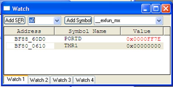
Before trying to execute the code, let's also open a Watch window and add the PORTD and TMR1 special-function regisiters to it.
Now you may manually step through the program using the Step In or Step Over buttons of the debugger toolbar or the Debugger -- Step In and Debugger -- Step Over commands from the main menu. You may also use Animate option from the top-level Debugger menu or the Animate button from the dialog toolbar to choose the animation mode. In this mode, the simulator executes one C program line at a time, pausing shortly after each line to give you time to observe the results in the Watch window.
The speed of execution in Animate mode can be controlled with the Debugger -- Settings... dialog box, shown below.
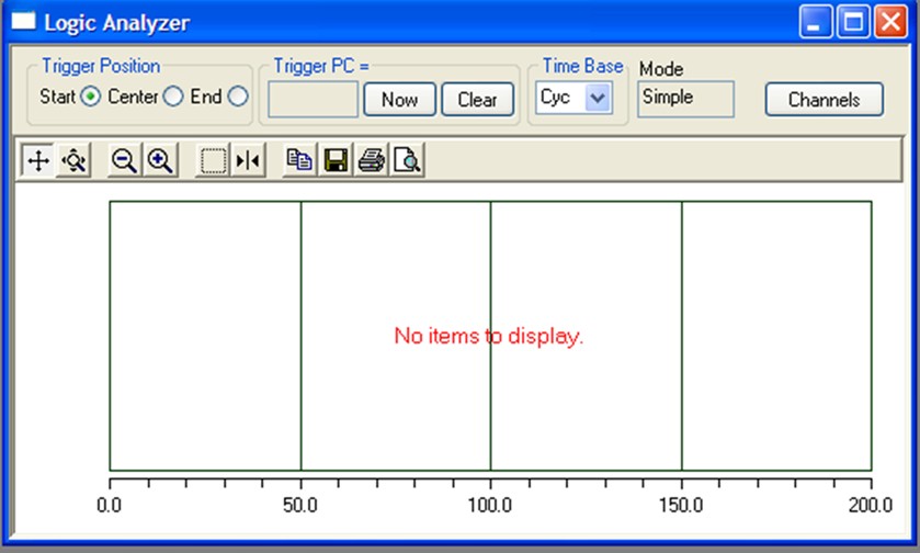
The MPLAB SIM Logic Analyzer gives you a graphical and extremely effective view of the recorded values for any number of the device output pins, but it requires a little care in the initial setup.
Before anything else, you should make sure that the Tracing function of the simulator is turn on:
You can run the simulation by pressing the Run button on the Debugger toolbar , selecting the Debugger -- Run menu item, or pressing the F9 shortcut key.
After a short while, press the Halt button on the Debugger toobar, or select the Debugger -- Halt menu item, or press the F5 shortcut key.
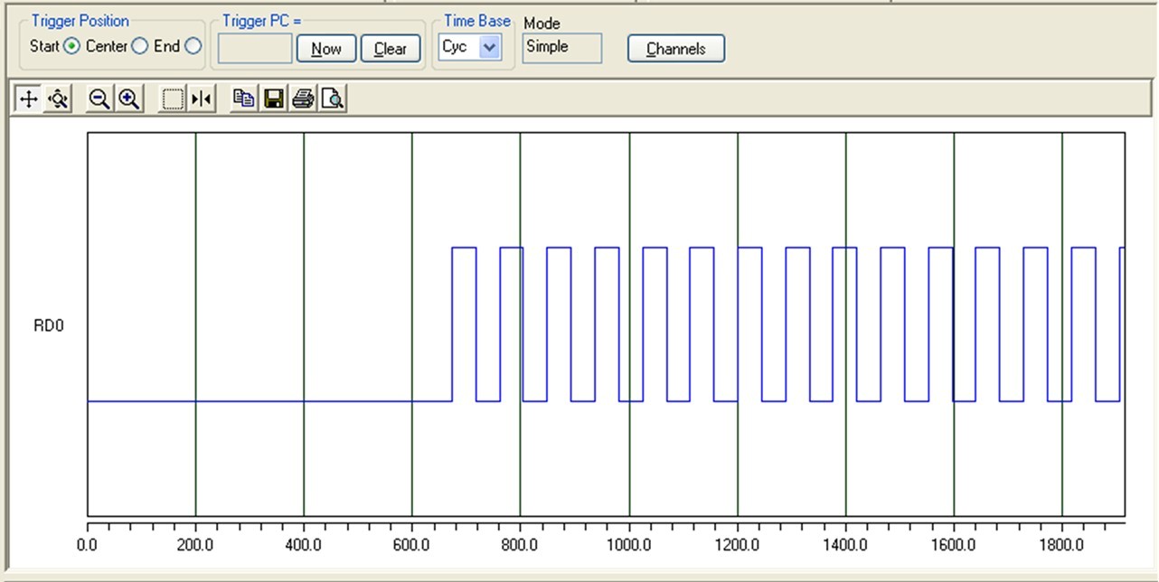
The logic analyzer should display its results (a square wave).
In our case, you may get better results by pressing the Animate button on the Debugger toolbar, or select the Debugger -- Animate menu item. The logic analyzer will now update continuously, and you can stop the display whenever you have collected enough information.
loops.c01: /* loops.c
02: *
03: * Use timer1 to blink an LED
04: * This like timer3.c, but is intended for simulation
05: * since the delay is so short.
06: */
07:
08: #include <plib.h>
09:
10: void wait();
11:
12: #define LED1 BIT_0 // LED1 is connected to RD0
13:
14:
15: int main()
16: {
17: int i;
18: mPORTDSetPinsDigitalOut(LED1); /* Make LED1 output */
19: mPORTDClearBits(LED1); /* Turn off LED1 on startup */
20: while (1) {
21: mPORTDToggleBits(LED1); /* Toggle LED1 */
22: wait();
23: }
24: return 0;
25: }
26:
27: void wait()
28: {
29: const int DLY = 10;
30: T1CON = 0x00; // turn timer off and set prescaller to 1:1
31: TMR1 = 0;
32: PR1 = 0xFFFF;
33: T1CONSET = 0x8000; // start timer
34: while (TMR1 < DLY) {
35: // just wait
36: }
37: T1CONCLR = 0x8000; // stop timer
38: }
The logic analyzer window shows the pin RD0 switching on and off, once execution has entered the LED-flashing while loop.
Lucio Di Jasio, Programming 32-bit Microcontrollers in C, Exploring the PIC32, Newnes (Elsevier), 2008. ISBN 978-0-7506-8709-5.
Pages 12-14 discuss using the simulator. Pages 35-37 discuss using the logic analyzer.
Maintained by John Loomis, updated Sat Aug 02 19:37:51 2008