EGR203 Assignment 6
- Suppose we have two Aluminum foil sheets (250 mm by 250 mm
square) with a 12-µm thick food wrap dielectric (estimated relative
dielectric constant of 2.5). Calculate the capacitance.
- Given two capacitors, one of 15 µF and the other 30
µF. Find the effective capacitance if the capacitors are
connected in series (end-to-end) and if they are connected in parallel
(side-by-side).
- A voltage of 50 V appears across a 10-µF capacitor. Determine
the amount of charge and the energy stored on the capacitor.
- Find the equivalent capacitance between terminals x and y
in the circuit below.
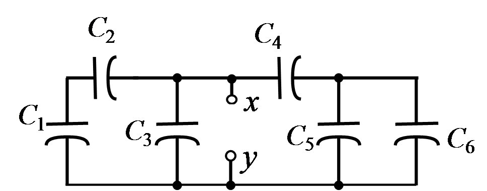
where
| C1 | C2 | C3
| C4 | C5 | C6
|
|---|
| 15 μF | 10 μF | 3 μF | 12 μF | 1 μF | 5 μF
|
- Suppose the time-varying voltage across a capacitor C =
10 µF is
V = 20 sin(200t). Find the time-varying current.
- Find the period and the average and rms value of
x(t) where
x(t) = 2 cos(8πt) + 5
- A 30V rms AC source is connected across a 50Ω resistor. Find
the average power dissipated in the resistor, and the amplitude of the
AC voltage.
- Given an ac voltage expressed as
v(t) = 4 sin(300t + 30°)
Express the voltage as a cosine function (instead of the sine
function).
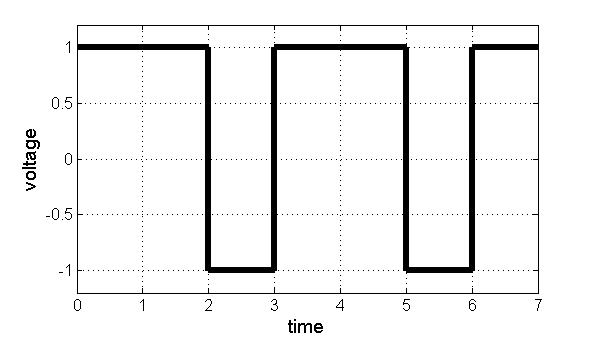
- Find the average value and rms value of the signal below.
Maintained by John
Loomis, last updated 4 June 2014