Quartus II software includes a system level debugging tool called SignalTap II that can be used to capture and display signals in real time in any FPGA design.
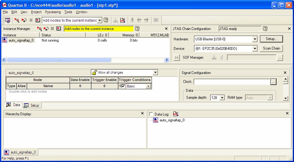
To use SignalTap II you must first import the DE2 pin assignments and compile the project. Then select the SignalTap II Logic Analyzer from the Tools dropdown menu. This brings up the following dialog. You may need to press Setup on the JTAG Chain Configuration pane and select the USB-Blaster hardware.
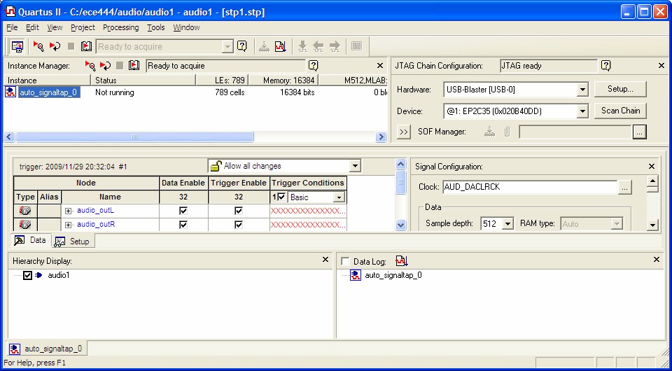
Select a clock signal (AUD_DACLRCK) in the Signal Configuration pane. Set the sample depth to the desired number of samples.
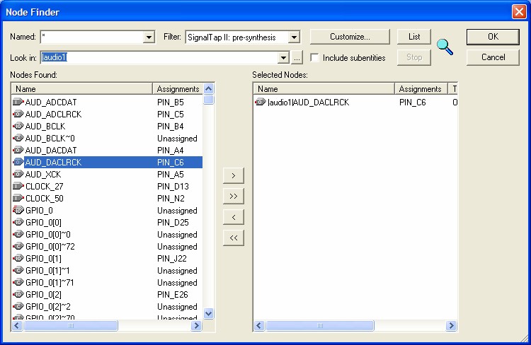
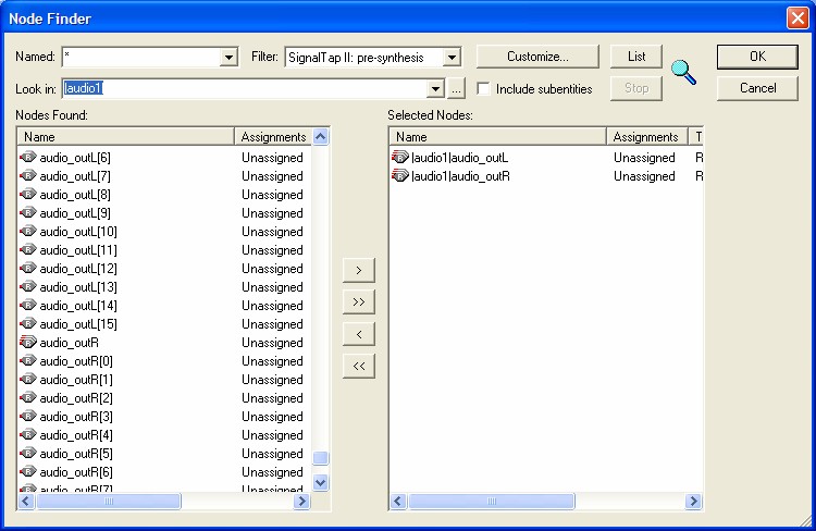
Add the nodes for display (audio_outL and audio_outR) as shown below.
Select the display format by right-clicking on each node. Select Bus Display Format, then signed decimal (two's complement) from the context menu.
Note that the signal used for the Clock cannot be analyzed and is removed from the list of signals if it was there.
If you get the message below, choose No.
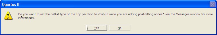
You must recompile the project after every change to the SignalTap
II configuration. Program the DE2 board as usual.
Select Processing – Run Analysis from the main menu or
click the Run
Analysis tool icon  from the instance
manager to obtain a single set of data.
from the instance
manager to obtain a single set of data.
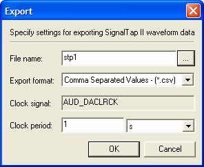
You can create a comma-separated-value (CSV) file for Excel by selecting File – Export ... to get the following dialog
Maintained by John Loomis, last updated 28 November 2009