ECE 201L Circuit Analysis Laboratory
Lab 5
This lab explores the transient and AC behavior of capacitors and inductors.
Do the following exercises. Report your results by writing a Word
document and submitting it in Isidore. Submit one
report per group.
- Pick two inductors from 1-10 mH. Measure the inductance of
two different inductors on the
impedance meter, separately, in series, and in parallel. Compare
measured values of series and parallel combinations with values
calculated from measurements of the individual inductosr.
| Component | Measured | Calculated
|
|---|
| L1 |
| n/a
|
| L2 |
| n/a
|
| L1 + L2 |
|
|
| L1 || L2 |
|
|
- Construct the following RC circuit. Use a resistance of 100-500Ω
and a capacitance of 1-100μF.
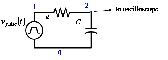
Use a function generator to produce a square wave and observe the signal
on the oscilloscope. Adjust the frequency to produce a waveform something like
the example below.
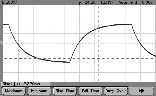
Display the frequency and rise and fall times on the measurement line. Capture
at least one image to include in your report.
Calculate the time constant from the rise/fall times,
trise = 2.2 τ. Also
calculate the time constant τ = RC. Explain or discuss any
differences between these calculations.
- Construct the following LR circuit. Use a resistance of
100-500Ω and an inductance of 1-10 mH.
.
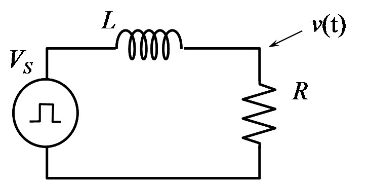
Use the oscillocope as before and
display the frequency and rise and fall times on the measurement line. Capture
at least one image to include in your report.
Calculate the time constant from the rise/fall times,
trise = 2.2 τ. Also
calculate the time constant τ = L/R. Explain or discuss any
differences between these calculations.
In each of the following exercises you will need to record the
following measurements from the oscilloscope.
- Frequency
- Peak-to-peak (amplitude) voltage of the input waveform
- Peak-to-peak (amplitude) voltage of the output waveform
- Phase difference between input and output
- Build the circuit shown below, using the same resistor and
inductor as in exercise 3 above. In this exercise, set the signal
generator for a sine wave.
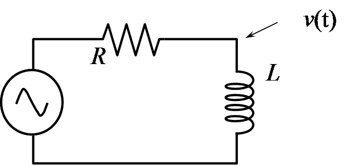
Vary the frequency until the phase shift is 45° and record
the AC response. The gain is the ratio of output amplitude voltage
to input amplitude voltage (Vout /
Vin).
- Replace the inductor with the capacitor from exercise 2 above, as in the circuit
below, and repeat the measurement.
| component | Frequency | Vin
| Vout | Ratio (gain) | Phase
|
|---|
| L |
|
|
|
|
|
| C |
|
|
|
|
|
The frequency recorded above, and the measured value of the
resistor can be used to calculate the capacitance or inductance.
Verify this calculation by comparing to the value measured on the
impedance meter.
| component | calculated value | measured value
|
|---|
| L |
|
|
| C |
|
|
- Construct the following circuit
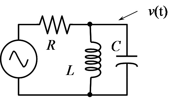
This is a resonant circuit. Adjust the frequency to give maximum
output signal. Record the AC response (voltage and phase). Change the
frequency higher and lower until the gain (ratio of output to input
amplitude) has dropped to 0.707 of the peak gain. Repeat the
measurement using a different resistance.
Case 1
| Frequency | Vin
| Vout | Ratio (gain) | Phase
|
|---|
|
|
|
|
|
|
|
|
|
|
|
|
|
|
|
Case 2
| Frequency | Vin
| Vout | Ratio (gain) | Phase
|
|---|
|
|
|
|
|
|
|
|
|
|
|
|
|
|
|
Component Measurements
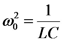
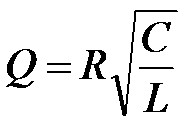
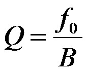
- Calculate the resonant frequency, bandwidth and Q values for the two sets of
measurements above. Bandwidth is the difference between the higher and
lower frequencies where the gain drops by 0.707 of its peak value.
Compare with the theoretical expressions for the resonant frequency and Q value:
| Case | Measured | Calculated
|
|---|
| Resonant frequency | Bandwidth | Q | Resonant
frequency | Bandwidth | Q
|
|---|
| 1 |
|
|
|
|
|
|
| 2 |
|
|
|
|
|
|
Maintained by John Loomis,
last updated 22 October 2012