ECE 201L Circuit Analysis Laboratory
Lab 3
This lab provides experience with
Attachment: lab3.doc.
Do the following exercises. Report your results by editing
the attached Word document and submitting it in Isidore and a printed
copy by the next lab. Submit one report per group.
- Install the applications InstaCal and TracerDAQ
from the MCC DAQ CD, which can be obtained from
the CDs in the lab or from the MCC downloads page.
- Follow the instructions given in the
installation guide
to install the DAQ.
- Measure the resistance of a photoresistor in the light and in the dark.
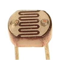
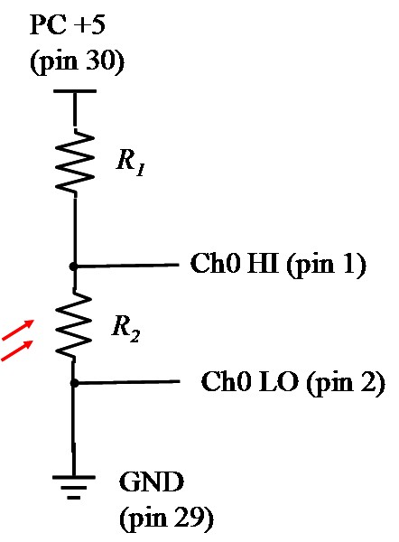
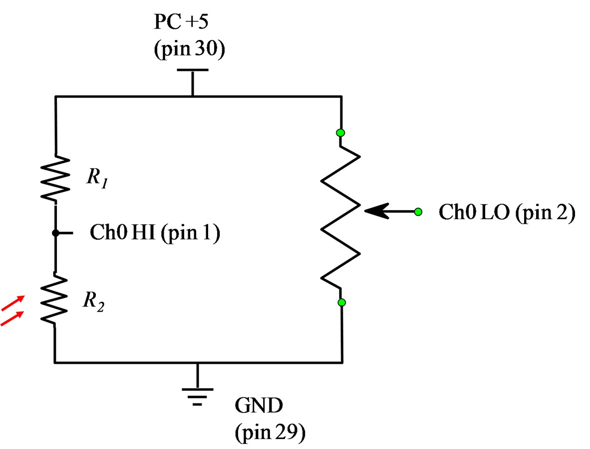
- Construct the circuit below. Make R1 be approximately the
average of the resistance readings above, typically
10KΩ or more. R2 is your photoresistor. You
may also try interchanging the position of the two resistors in the
voltage divider. Measure the voltage between pin 1 and pin 2 using a multimeter
in the light and in the dark. Compare the voltage results to calculated values based on
measured resistances.
- Run the program TracerDAQ and its strip chart function. Capture some representative data, using
your hand to cover and uncover the photoresistor.
See TracerDAQ instructions.
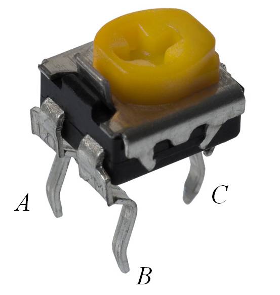
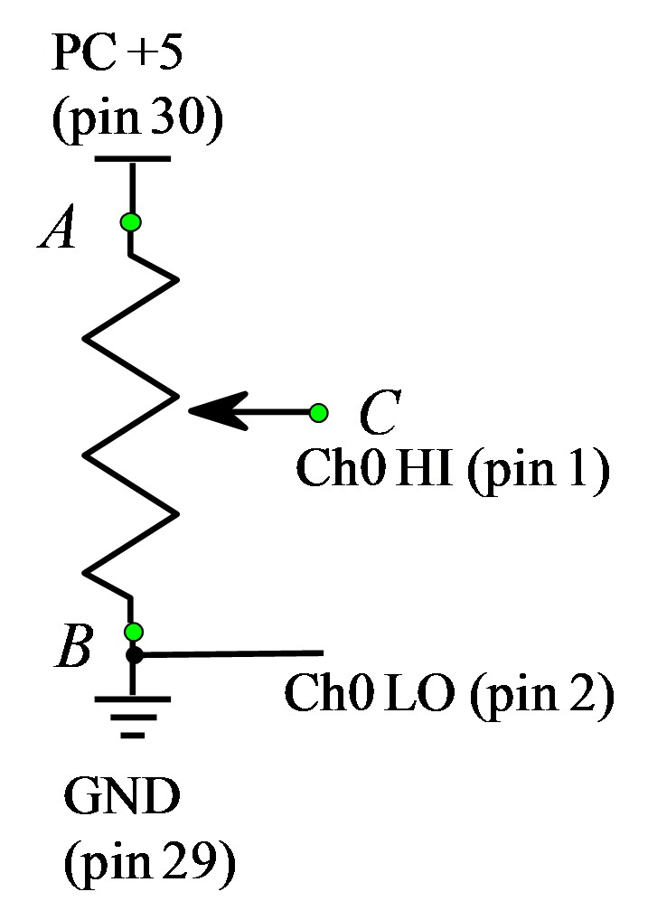
- Construct the circuit below. Do not remove the previous circuit, because you will need it later.
Verify that you can vary the voltage at C from 0 to 5 V
by adjusting the trimpot. Demonstrate this using TracerDAQ by ramping the voltage up and down over
the full range, capturing a screen image, and including it in your report.
- Construct the circuit below (Wheatstone bridge). Adjust the trimpot so that the response in the
light and in the dark are centered about zero. Capture some representative data using TracerDAQ and while you use your
hand to cover and uncover the photoresistor.
- Use the strobe light provided by the lab assistants, with the speed set at the white dot.
Use TracerDAQ to acquire a few seconds of data from the bridge circuit. Analyse the captured data
in Excel and determine the flash rate.
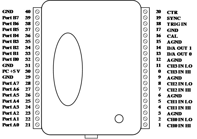
Data Acquisition Board Pinout
Maintained by John Loomis,
last updated 27 January 2012