Download rs232lab.zip
This project uses the RS232 interface on the DE2 board to send serial data from one board to another or, using either hardware or software loopback, to send and receive data on a single board.
To send data from one board to another, you will need to connect the two boards with a DB9 (9-pin D-SUB connector) male-male null modem cable. Null modem means that pin 2 (TXD) is connected to pin 3 (RXD) and vice versa.
To send and receive data on a single board, use a single DB9 male connector with pins 2 and 3 wired together OR modify the Verilog code so that the output of the RS232_Out module is wired internally to the input of the RS232_In module, bypassing the external UART.
To send individual characters, press KEY3 on the DE2 board. You can also send characters at 1 per second by setting SW0 “On”.
The default message contains the hexadecimal digits, in order, and a few lines of “Row, row, row your boat”. A C program is provided to generate other messages in MIF format.
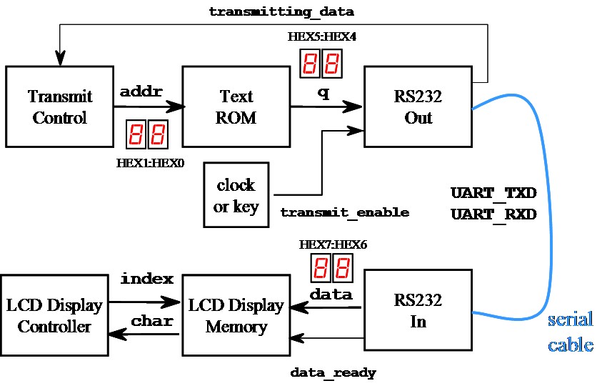
The overall organization of the project is shown below:
Transmit control waits for the serial output of the current character to complete and then increments the address of the text ROM. The rate of transmission is determined either by key press or by the output of a 1-second clock.
The data format is 8-bits with a start bit and a stop bit and a fixed baud rate of 115.2 kbits/second.
The text rom is initialized with a MIF file created by the program
miftext.cpp.
The LCD display memory stores two lines of 16 characters each. It is updated by the RS232_In module. The LCD controller continuously updates the LCD display.
We can attach oscilloscope leads between pin 2 and pin 5 (ground) and observe the resulting waveform (see below). The character rate was greatly increased so that three characters can be seen on the same screen.
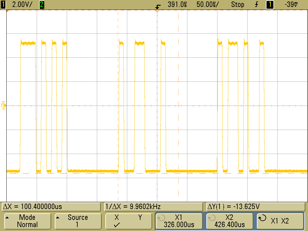
The minimum voltage (logic 1) is about -5.5 Volts. The maximum voltage (logic 0) is about +5.5 Volts. The receive process is triggered by a start bit (low to high transition) which starts the baud clock. Each pulse is 1/ 115.2k = 8.68 µseconds wide. The pulse is first sampled half-way through the pulse (4.34 µseconds from the start of the baud clock) and then every 8.68 µseconds. The stop bit returns the output to its normal (low) voltage.
rs232lab:
Verilog source code and Quartus Compilation reports.
The Altera University Program IP Core, RS232 UART, provided some inspiration for this project. Download RS232.zip to see the IP core.
Maintained by John Loomis, last updated 18 November 2009