
Download: ramtest.zip
This project tests the memory access actions of a simple computer. The load instruction (Opcode 0x01) reads data from a specified memory address into the accumulator. The store instruction (Opcode 0x04) writes data from the accumulator into a specified memory address.
Memory can be examined in the simulator after running the program by clicking on the Logical Memories section in the left column of the simulation report tree list.
| Instruction Mnemonic | Operation Performed | Opcode |
|---|---|---|
| LOAD address | AC ← contents of memory address | 01 |
| ADD address | AC ← AC + contents of memory address | 02 |
| SUB address | AC ← AC − contents of memory address | 03 |
| STORE address | contents of memory address ← AC | 04 |
| JUMP address | PC ← address | 05 |
| JNEG address | If AC < 0 then PC ← address | 06 |
C = A + B
If we assume that A is stored in address 0x10, B is in address 0x11, and the result C should be stored in 0x12, then we have the following program:
| Assembly Language | Machine Language |
|---|---|
| LOAD B | 0111 |
| ADD A | 0210 |
| STORE C | 0412 |

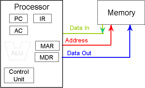
| PC | Program counter |
|---|---|
| IR | Instruction register |
| AC | Accumulator |
| MAR | Memory address register |
| MDR | Memory data register |
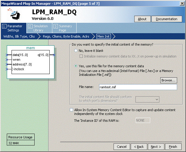
DEPTH = 256;	% Memory depth and width are required	%
WIDTH = 16;	% Enter a decimal number	%

ADDRESS_RADIX = HEX;	% Address and value radixes are optional %
DATA_RADIX = HEX;	% Enter BIN, DEC, HEX, or OCT; unless %
			% otherwise specified, radixes = HEX	%
-- Specify values for addresses, single address or range
CONTENT
	BEGIN
[00..FF]	:      0000;  % Range--00 to FF = 0000 %
   00		:      0112;  % Load MEM[12] %
   01		:      0110;  % Load MEM[10] %
   02		:      0412;  % Store MEM[12]%
   03           :      0111;  % Load MEM[11] %
   04		:      0112;  % Load MEM[12] %
   05		:      0113;  % Load MEM[13] %
   10		:      0AAA;
   11		:      0BBB;
   12		:      0123;
   13          :      0DDD;
END ;
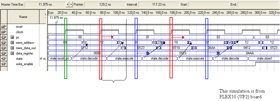
always
case (state)
reset_pc: mem_address <= 8'h00;
decode:  mem_address <= mem_data_out[7:0];
execute: mem_address <= pc;
store1:  mem_address <= data_address;
store2:  mem_address <= pc;
default: mem_address <= 8'hff;
endcase
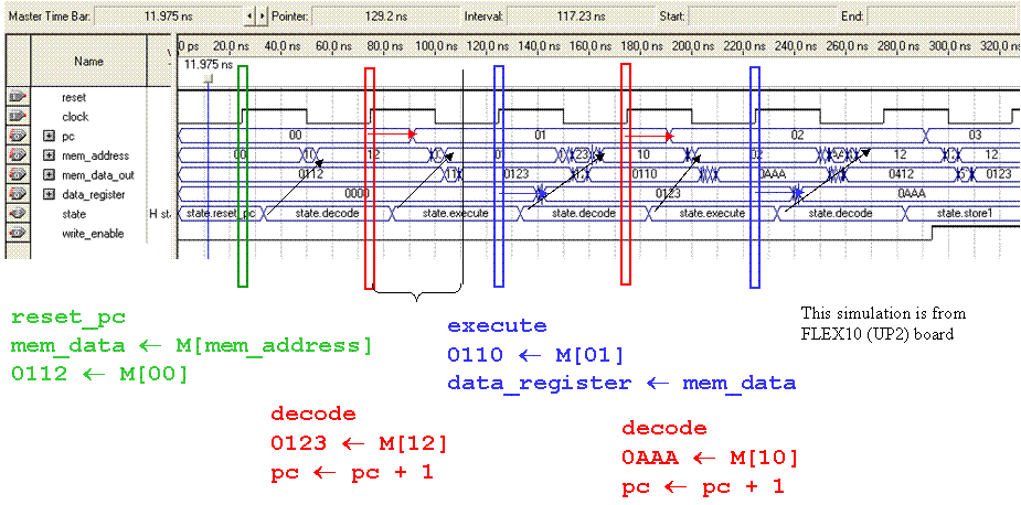
mem_address changes when state changes (combinational process)
always @(posedge clock, negedge reset)
	begin
	if (~reset) state<=reset_pc;
	else
	case (state)
	reset_pc :
		begin
		pc <= 8'h00;
		data_register <= 16'h0000;
		state <= decode;
		end
// decode opcode, increment program counter
	decode :
		begin
		pc <= pc + 8'h01;
		data_address <= mem_data_out[7:0];
		// decode opcode
		case (opcode)
		8'h01 : // load
			state <= execute;
		8'h04 : // store
			state <= store1;
		default:
			state <= decode;
		endcase
		end
// execute instruction, save data
	execute :
		begin
		data_register <= mem_data_out;
		state <= decode;
		end
	store1 : state <= store2;
	store2 : state <= decode;
	// default state transition
	default : state <= decode;
	endcase
	end
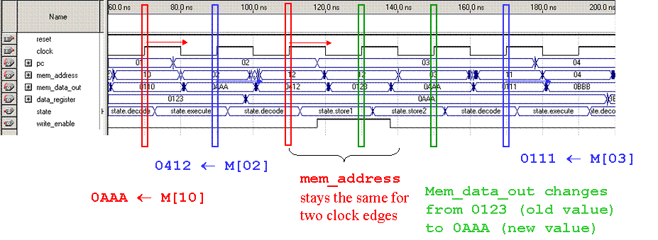
assign write_enable = (state==store1);
ramtest.v
module ramtest(clock, reset, mem_address, mem_data_out,
data_register, pc, write_enable);
input clock, reset;
output [15:0] mem_data_out;
output [15:0] data_register;
output [7:0] pc;
output [7:0] mem_address;
//output [2:0] state;
reg [2:0] state;
reg [15:0] data_register;
reg [7:0] pc;
reg [7:0] mem_address;
reg [7:0] data_address;
output write_enable;
wire [7:0] opcode;
assign opcode = mem_data_out[15:8];
parameter
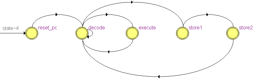
reset_pc = 3'd0,
decode = 3'd1,
execute = 3'd2,
store1 = 3'd3,
store2 = 3'd4;
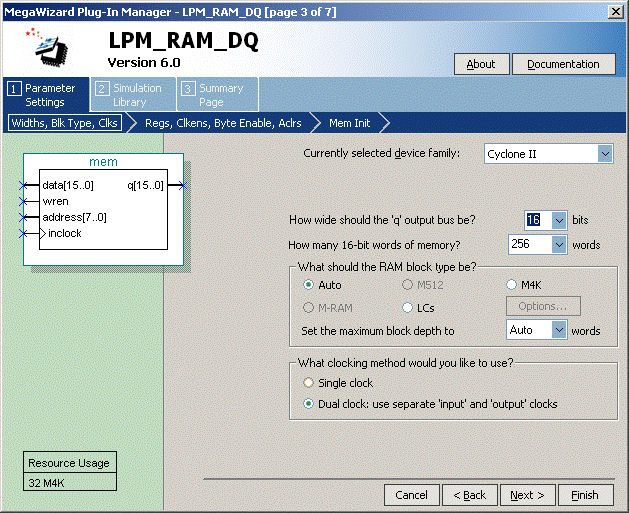
// instantiate memory (256 16-bit words)
mem mem_component(
.address (mem_address),
.data (data_register),
.inclock (clock),
.wren (write_enable),
.q (mem_data_out)
);
//assign write_enable = (state==store1?clock:1'b0); // this fails
assign write_enable = (state==store1); // this works
always
case (state)
reset_pc: mem_address <= 8'h00;
decode: mem_address <= mem_data_out[7:0];
execute: mem_address <= pc;
store1: mem_address <= data_address;
store2: mem_address <= pc;
default: mem_address <= 8'hff;
endcase
// finite state machine
always @(posedge clock, negedge reset)
begin
if (~reset) state<=reset_pc;
else
case (state)
reset_pc :
begin
pc <= 8'h00;
data_register <= 16'h0000;
state <= decode;
end
// decode opcode, increment program counter
decode :
begin
pc <= pc + 8'h01;
data_address <= mem_data_out[7:0];
// decode opcode
case (opcode)
8'h01 : // load
state <= execute;
8'h04 : // store
state <= store1;
default:
state <= decode;
endcase
end
// execute instruction, setup instruction address
execute :
begin
data_register <= mem_data_out;
state <= decode;
end
store1 : state <= store2;
store2 : state <= decode;
// default state transition
default : state <= decode;
endcase
end
endmodule
Maintained by John Loomis, last updated 7 October 2008